
Home » AKCP Blog » Design and Build a Data Center – Inside AKCP’s Physical Twin
Design and Build a Data Center - Inside AKCP’s Physical Twin
How does a cooling design perform when the heat load changes? What happens when airflow is uneven across a rack? And how closely does a digital model reflect conditions inside a physical facility?
These are the questions we are building AKCP’s 1 MW Physical Twin Test Data Center to investigate. In our latest video, AKCP President Nicholas Barrowclough takes you through the facility as it approaches commissioning, explaining the cooling systems, adjustable heat loads, and monitoring infrastructure that will support our experiments.
The facility gives our engineering team a controlled environment for testing different data center configurations and measuring their performance. We can change heat loads, adjust airflow, reconfigure water circuits, and observe the results without disrupting a customer’s production infrastructure.
The first phase focuses on a hot aisle containment pod with ten racks. Each rack contains three independently controlled 9 kW heaters, providing up to 27 kW per rack and a combined heat load of 270 kW across the pod. This is the initial test configuration within the wider 1 MW facility project.
Independent heater control lets us vary where heat is generated within each rack. We can concentrate the load at the top, middle, or bottom, or distribute it more evenly. Variable-speed fans also allow us to adjust airflow through the racks and investigate the relationship between heat load, air movement, and pressure.
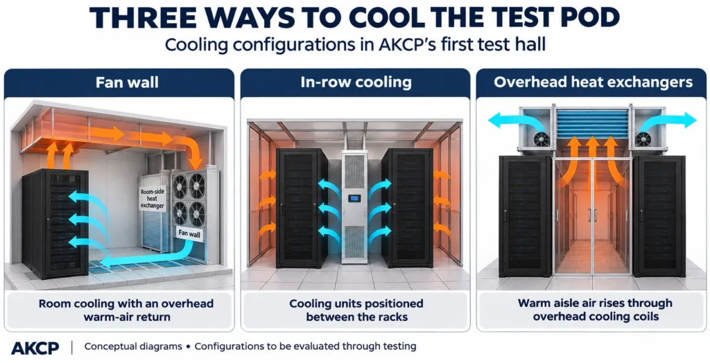
The first hall incorporates three cooling approaches: a fan wall, in-row air handling units, and overhead heat exchangers. The fan wall supplies cooled air to the room and receives warm return air through an overhead plenum. The in-row units provide cooling between the racks. Above the containment aisle, heat exchangers cool the rising exhaust air, with fans assisting its passage through the coils.
Having these options in one facility allows us to investigate how each arrangement responds to different operating conditions. The aim is to understand which configurations work well for a particular load and layout, and what the measurements reveal when conditions change.
The water system provides similar flexibility. A 250 kW chiller supplies an insulated storage tank, while outdoor dry coolers offer another route for rejecting heat. Depending on water temperatures and the requirements of an experiment, water can return directly from the dry coolers to the data center or pass through the chiller for additional cooling.
For the air-cooling setup described in the video, the target supply water temperature is approximately 23°C. When the dry coolers can meet that requirement, the system can bypass the chiller. When they cannot, they may still remove some heat before the water reaches it. The facility will let us measure the contribution of each stage under different conditions.
The piping also supports experiments involving both building cooling and data center cooling. Separate pump groups and configurable valves allow independent circuits or a series arrangement in which water passes through the building’s cooling system before serving the data center, where temperatures permit. Water quality is a key part of preparing this system for operation. The tour includes self-cleaning filters, reverse osmosis equipment for makeup water, and a chemical monitoring and dosing system. With aluminum heat exchangers and other metals sharing the circuit, managing water chemistry is an important part of protecting the equipment.
Throughout the facility, AKCP sensors provide the measurements needed to interpret each experiment. Temperature and pressure monitoring help us follow conditions through the system, while automated valves allow configurations to be selected through Quicklime. This physical infrastructure supports a corresponding digital twin, connecting the equipment and its operating conditions with a software representation.
Further configurations are planned for the second hall, including cold aisle containment and a smaller raised-floor pod supplied by underfloor cooling. These additions will broaden the range of customer environments we can reproduce and study.
At the time of filming, the electrical systems had been installed and tested, pipework leak testing was complete, and chemical water treatment was beginning. The next step was to circulate the treated water for 48 hours before progressing to integrated system testing.
That next phase will bring the individual systems together under load. We look forward to sharing the measurements, practical lessons, and results as experiments begin.
Follow AKCP’s video updates to see the Physical Twin progress from construction to testing, and explore our monitoring solutions to learn how measured data can help you understand your own facility.
- About the Author
- Latest Posts

Nicholas Barrowclough( President )
For over two decades at AKCP, I have been focused on a single mission: bringing complete visibility, security, and efficiency to the world’s critical infrastructure.
I believe that in the modern data center, AI is only as good as the data it receives. My goal is to ensure facilities have the precise sensor facts needed to control AI opinions, ultimately reducing PUE, releasing stranded capacity, and ensuring maximum uptime.