In any data center, regardless of its cooling technology, the biggest operational cost is that of the cooling.
In this article we will provide some best practices information, to improve the efficiency of the cooling and reduce the costs.
With the most widely used cooling solutions which are some form of air cooling, the most critical factor is the efficient management of the airflow. It is important to note that any changes made to the IT equipment cooling in a live business environment have to be planned and executed carefully. Be sure to understand the effects, and consult experienced engineers before actually making the changes.

Gathering preparatory metrics
You should analyze and observe the current situation of your data center’s cooling, before reading the other sections.
- Determine the currently used IT load in kilowatts.
- Measure intake temperatures across the data center, also include the hot spots. You should at least record the temperature at the mid-height and at the end of each row of IT racks, and then at the top of a rack in the center of each row. Record the locations, the temperatures and the date/time of each measurement. The collected data will be later used for comparison.
- Measure the power draw (in kilowatts) that is used to operate the cooling units. On most units, there is a dedicated panel for measurement. This information could be also accessible from a separate monitoring system. The collected data will be later used for comparison, and for the calculation of kilowatt-hours and long-term cost savings.
- Measure the room’s sensible cooling load. You can do this by measuring the airflow volume for each cooling unit, and record the supply- and return temperatures for each running (active) unit. You can calculate the reasonable capacity of each operating unit in kW for each unit with the expression:
Q sensible (kW) = 0.316*CFM*(Return Temperature[°F] – Supply Temperature[°F])/1000 [Q sensible (kW) = 1.21*CMH*(Return Temperature[°C] – Supply Temperature[°C])/3600]
The room’s sensible cooling load is the sum of each cooling unit which is running in the room. You can organize the collected data in a spreadsheet, to record each data point, the supply and the return temperature, ΔT (return-supply), also the airflow, sensible kilowatt and then sum to provide the overall room sensible load. Don’t forget to also confirm that the entire IT load is being supplied by the cooling system and that there is no additional IT load which is in another room, then finally check that the cooling plant is not supporting any non-IT load.
Then you can compare the cooling load to the IT load used, as a point of reference.
- Using the airflow and the return air temperature measured in the previous #4 step, contact your equipment vendor and request the sensible capacity of each unit in kilowatts. Then enter this nominal sensible capacity in your spreadsheet. Sum the sensible capacity for the units that are currently operating. This will be a quick and easy approximation of the sensible-cooling capacity of the cooling units which are in use. There are more complex methods for calculation (you may search online), but for simplicity reasons, we don’t include them.
- Now divide the overall room operating cooling sensible capacity in kilowatts that you determined in the previous step #5 by the sensible operating cooling load that was determined in step #4. The resulting number presents a simple ratio of the operating capacity VS the cooling load. This ratio could be as low as 1.15 (where the cooling capacity matches your IT load, with one cooling unit in six redundant), but most likely it will be much higher. This ratio can be considered as a benchmark to evaluate the subsequent improvement, as the reduction of this ratio will occur linearly with the reduction of the operating cooling units.
- Consulting with IT engineers, determine the maximum allowable intake temperature (that is not damaging the IT equipment) for the new operating environment. For temperatures above 75°F / 24°C, there could be offsetting power increases within the IT devices, coming from their onboard cooling fans.
- Using the data gathered above, create a work plan outlining your goals of the effort, and detail the metrics that will be monitored to ensure the cooling environment is not disrupted. You will also need to specify a back-out plan in case a problem is discovered. Finally, identify the performance metrics that will be tracked for the rack inlet temperatures, the power consumption, etc. Remember that this plan should be fully communicated and discussed with IT personnel and with other members of the critical operations team.
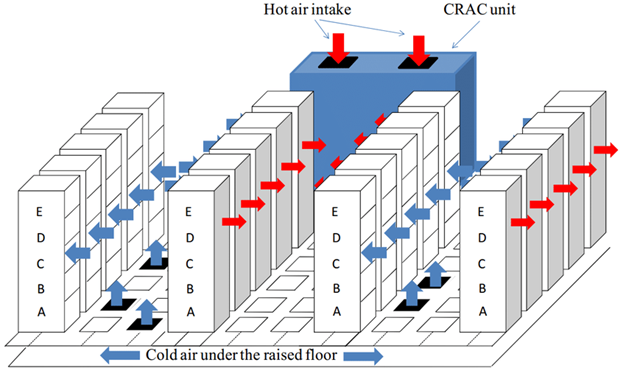
Image source researchgate.net, Data Center Cooling Topology
The initial action to manage airflow
After gathering the initial data and your current values for comparison, you may take some actions for improvement.
- Relocate all of the raised-floor perforated tiles to the Cold Aisle. Any perforated tile that is supporting a given rack should be placed immediately in front of the rack for the best cooling airflow. As a starting point, each rack containing IT equipment which are producing any cooling load, should have a single perforated floor tile in front of them. The empty racks, and racks with no electrical load installed in them should have a solid tile (blank) in front of them to reduce the wasted cooling energy. However, you should give special attention to racks with network equipment installed like switches or patch panels – these devices can also generate a lot of heat.
- If you are using return air plenums, ensure that the placement of the ceiling return grilles will align with the Hot Aisles.
- Seal the vertical front of the racks that are not housing equipment with blanking plates or other similar methods, to prevent any Cold Aisle air from moving through these empty rack positions into the Hot Aisle and reduce the cooling efficiency.
- Seal any cable holes in the raised floor, if you use them.
- Seal any holes in the walls, or the structure surrounding the computer room. Also check the walls below the raised floor, and above the ceiling for holes. Check for any unsealed openings in the structure under- or over the entire computer room. The most common issues are from conduits, cables or pipes entering the computer room.
- If the cooling units reside in the computer room. seal any supply air leakage around these units.
- Ensure that all online cooling units in the room are equipped with a backflow damper, and you should fabricate covers for the offline units to prevent the backflow of cooling through the powered-off cooling units.
- Seal any leakage of the cooling air at the power distribution units, at distribution panels or at any other electrical devices which are mounted on the raised floor.
- Record the temperatures again at the same locations as in step #2. Compare this and your prior readings to determine if any of the intake temperatures have increased. If an increase is observed, you will need to increase the airflow to the rack(s) with the problem by moving a raised-floor perforated tile from a non-hot spot area, or by replacing the standard perforated floor tile with one that has a higher flow rate.
Action A: Reduce the number of online cooling units by shutting units off
- Identify the cooling units which are having the lowest sensible load. These units will be the first ones to be turned off, as the following process is implemented.
- Estimate the number of the required cooling units, by dividing the full IT load by the smallest sensible cooling unit capacity. This will approximate the number of the online cooling units necessary to support the IT load.
- Based on Uptime Institute’s recommendations, the cooling redundancy in large computer rooms should be 1 redundant unit for every six cooling units. However, smaller or otherwise oddly shaped rooms might require a higher level of redundancy. You should divide the required number of cooling units by six, to determine the number of redundant cooling units. Then round up this value to the next higher whole number. The result is the suggested number of redundant cooling units for the IT load.
- Add the results of the two previous steps #19 and #20. This result will be the desired number of the cooling units necessary to operate to meet the IT load and to provide 1:6 redundant cooling units. This number should be fewer than the total number of installed cooling units.
- Turn off one operating cooling unit each week one by one, until only the desired number of cooling units determined in the previous step #21 will remain online. However, watch for the temperature increase.
- With each ‘excess’ cooling unit being put offline, examine reducing the number of perforated tiles on the floor to match the now reduced airflow being supplied to the room.
If a temperature increase is observed, you will need to increase the airflow to the rack(s) with the problem by adding additional raised-floor perforated tiles, or by replacing the standard perforated floor tile with one that has a higher flow rate. The placement of the floor tiles to appropriately match the cooling supply is an iterative process, so take your time.
- Before each subsequent reduction in the number of online cooling units, again record the temperatures at the same locations as you did in step #2. Compare this and your prior readings to determine if any server’s intake temperatures may have increased. If an increase is observed, you will need to increase the airflow to the rack(s) with the problem by moving a raised-floor perforated tile from a non-hot spot area, or by replacing the standard perforated floor tile with one that has a higher flow rate.
- When the desired number of online cooling units has been reached, record the power draw for these units as in step #3. This might be also possible through any existing monitoring. Now compare the before- and after modification values, to observe the reduction in the power draw.
Action B: Gradually raise the temperature in the computer room
- Increase the temperature set point on each cooling unit by one or two degrees a week, until the server intake air is at the desired level. The highest server intake temperature should be around 75°F / 24°C. To accomplish this setting faster and get a greater rate of change, you would need to consult and discuss with the data centre’s IT personnel and the integrated operations team.
Note that this step can be also completed regardless of whether the currently used cooling unit uses supply- or return air control. If the unit has return air control then the setpoint might seem quite high, but the supply air value will be in the acceptable range.
- Before each subsequent increase in the cooling setpoint temperature, again record the temperatures at the same locations as you did in step #2. Compare this and your prior readings to determine if any server’s intake temperatures may have increased. If an increase is observed, you will need to increase the airflow to the rack(s) with the problem by moving a raised-floor perforated tile from a non-hot spot area, or by replacing the standard perforated floor tile with one that has a higher flow rate.
Action C: Review the results and report metrics
Re-create the preparatory metrics measurements from steps and compare them to the original starting values. This also includes the following metrics:
- The total cooling unit power consumption
- The ratio of the operating cooling capacity and the cooling load
- The IT equipment inlet temperatures
Calculate the resulting overall power savings based on the implemented measures you made, and estimate the annual IT operations savings based upon the reduced kilowatt-hours and the average cost of utility power. Finally, you can report the progress and results too the integrated data center operations team.