sensorProbe+ Series Knowledge Base (SP2+ SPX+)
SETUP & LOG IN, SECURITY & NMS
Note: This will also not apply to the F4 type units (final firmware version supported is v1.0.5606).
Please follow the directions in this SP+ setup video or the image for first connecting your unit:
https://www.youtube.com/watch?v=OtrccRpm1cw
Important Note: If you do not have a DHCP server, or do not use DHCP then the unit will only try DHCP for a few seconds, if there’s no reply it will fall back to the default IP address of 192.168.0.100. Then you can use the direct cross over cable connection to your laptop or PC. Or simply connect the unit to your network switch and type in the default IP address above in your browser. This also applies if you are using the SP+ F4 or F7 type units.
Please note: The example in the video above shows our SP1+ unit. These steps will be the same for all SP+ (SP2+ & SPX+ H7) units shipped with firmware v1.0.5824.
Additional Options for Connecting to your SP+ Units Web UI
Option #1. If using DHCP check your network router’s DHCP assignments list.
How do I find the DHCP list on my router? (the following may be different depending on your router type)
Click the Status tab after logging into your router, then the Local Network sub-tab. Click the DHCP Client Table button under the DHCP Server section. This should bring up a list of clients that are currently connected to your network. You should see your SP+ or unit in this list.
After identifying the IP address assigned, open your browser and type in the IP address.
Option #2. Use the IPSet utility (also applicable for the F4 & F7 type SP+ units).

A. You can also try using our IPSET utility which you can download using the QR code or direct link here:
http://www.akcp.in.th/downloads/Firmwares/lnuxIPSet6.0.0.zip
B. Start the IPSET utility. Press the “reset” button on the sensorProbe+ or SP-WTS unit once. IPSET will detect the units IP address and allow you to open the units web interface.
Option #3. If you have our AKCP LCD display sensor.
Connect the LCD display to any sensor port on the unit. The IP address will be displayed in the LCD panel.
Option #4. If you are NOT using a DHCP server (after the unit has reverted back to the default IP address). Also applicable for the F4 & F7 type SP+ units.
Connect your SP+ unit directly to your network switch with a direct connect CAT5/6 cable and type in the default IP address of 192.168.0.100.
Re-assign your desired IP address in the Network settings as shown in the SP+ manuals.
VERY IMPORTANT NOTE: If you connect your SP+ (firmware versions beginning with 1.0.5824 or higher) unit directly to your laptop or PC using a cross over cable, DHCP will be temporarily disabled.
If you do not log into the unit’s web UI and set a fixed IP address, then if you re-connect the unit to your network switch (using a straight through cable), DHCP will be re-enabled again. This does NOT apply to the F4 or F7 type SP+ units or any H7 type SP+ units currently in the field prior to firmware v1.0.5824, or upgrading to the v1.0.5824.
Troubleshooting & Connection Problems
A. Make sure you can ping the units assigned or default IP address.
B. Make sure your laptop, PC or network fixed IP is configured for the default network subnet as the unit (192.168.0.1 for example). And that the IPv4 is checked/enabled on your PC.
C. Check the Ethernet link LED on the unit and the PC. Check the patch cable (direct connect = crossover. Connect to switch = straight through).
D. Try temporarily disabling your Antivirus & Firewall.
E. You can also try using our IPSET utility as described above.
IMPORTANT NOTE: If you have performed a complete factory reset on your SP+ H7 type (on firmware v1.0.5824 or higher) unit without choosing the option to retain the fixed IP address, then your unit will default back to DHCP. Please refer to the steps above again to determine your units newly assigned IP address.
Note: In some cases, your computer might not be able to connect to this default IP address. In this situation you either need to:
a) add this IP your computers routing table or
b) add a secondary IP address to the LAN card to allow access to the unit.
See below how to setup these.
Ensure the following items are available to you before starting:
– RJ45 CAT5 crossover cable with RJ45 male connection
– A PC with Ethernet card or LAN socket, logged in with Administrator rights
1) Connect the unit via the Ethernet port of the unit to your computers LAN or Ethernet port with a CAT5 crossover cable.
2) Open a web browser and type the default IP address, hit enter.
You’ll be presented by the Summary page.
Go to the System/Network page to change the network settings (see below in this manual).
Once you have assigned the new IP address use the “ping” command to test the unit’s reply.
How to add a manual route to the computer’s routing table?
Open an Administrator Command Prompt (CMD) window and type:
route add 192.168.0.100 10.1.1.20
Where 10.1.1.20 is the IP address of the Ethernet interface on the PC that the unit is plugged into with the crossover cable.
Note: If you do not receive an ‘OK!’ message then a parameter was wrong or missing.
The route is not persistent (removed upon rebooting), but you can also delete it with the
route delete 192.168.0.100 command.
How to add a secondary IP address to the computer’s LAN card?

You can do this via the GUI by opening the LAN connection’s properties:
Or open an Administrator Command Prompt (CMD) window and type:
netsh interface ipv4 add address “Local Area Connection” 192.168.0.2 255.255.255.0
The above command adds the IP Address 192.168.0.2 (with Subnet Mask 255.255.255.0) to the connection titled “Local Area Connection”.
You will then be able to connect to the unit with its default IP.
Note: The secondary IP address is permanent for the LAN connection; don’t use it if you only need it once. Instead use the routing table method above.
Please note the details explained above regarding first connecting to your unit’s web interface.
After successfully connecting to your SP+ web interface, please check both the SP+ Introduction and the Notification manuals on the exact steps for setting up your unit, configuration of your sensors and notifications here;
http://www.akcp.in.th/downloads/Manuals/SP2+/SP2+%20Introduction%20Manual.pdf
http://www.akcp.in.th/downloads/Manuals/SP2+/SP2+%20Notifications%20Manual.pdf
http://www.akcp.in.th/downloads/Manuals/SP2+/SP+%20Email%20Alerts%20Quick%20Start%20Guide.pdf

- Start the IPSET utility. Press the “reset” button on the sensorProbe+ unit once. IPSET will detect the units IP address and allow you to open the units web interface and set your IP address.

If you have any further issues with connecting to your unit, please check the sensorProbe+ connection troubleshooting steps below & in the SP+ manuals, or contact our support team for more assistance.
- Make sure you can ping the units default IP address.
- Make sure your laptop, PC or network fixed IP is configured for the default network subnet as the unit (192.168.0.1 for example). And that the IPv4 is checked/enabled on your PC.
- Check the Ethernet link LED on the unit and the PC. Check the patch cable (direct connect = crossover. Connect to switch = straight through).
- Try temporarily disabling your Antivirus & Firewall.
How do I find the DHCP list on my router? (the following may be different depending on your router type)
Click the Status tab then the Local Network sub-tab. Click the DHCP Client Table button under the DHCP Server section. This should bring up a list of clients that are currently connected to your network. You should see your SP+ or SP-WTS unit in this list.
After identifying the IP address assigned, open your browser and type in the IP address.
Option #2. Use the IPSet utility (also applicable for the F4 & F7 type SP+ units).
F. You can also try using our IPSET utility which you can download using the QR code or direct link here:

http://www.akcp.in.th/downloads/Firmwares/lnuxIPSet6.0.0.zip
G. Start the IPSET utility. Press the “reset” button on the sensorProbe+ or SP-WTS unit once. IPSET will detect the units IP address and allow you to open the units web interface.
Option #3. If you have our AKCP LCD display sensor.
Connect the LCD display to any sensor port on the unit. The IP address will be displayed in the LCD panel.
Option #4. If you are NOT using a DHCP server (after the unit has reverted back to the default IP address). Also applicable for the F4 & F7 type SP+ units.
Connect your SP+ unit directly to your network switch with a direct connect CAT5/6 cable and type in the default IP address of 192.168.0.100.
Use the IPSet utility in the steps noted above with the unit directly connected to your notebook or PC using a cross over cable.
Re-assign your desired IP address in the Network settings as shown in the SP+ & SP-WTS manuals.
VERY IMPORTANT NOTE: If you connect your SP+ (firmware versions beginning with 1.0.5824 or higher) unit directly to your laptop or PC using a cross over cable, DHCP will be temporarily disabled.
If you do not log into the unit’s web UI and set a fixed IP address, then if you re-connect the unit to your network switch (using a straight through cable), DHCP will be re-enabled again. This does NOT apply to the F4 or F7 type SP+ units or any H7 type SP+ units currently in the field prior to firmware v1.0.5824, or upgrading to the v1.0.5824.
Also see above for troubleshooting connection issues as well.
Here is the list pressing and holding in the reset button:
3 seconds = Shows IP and broadcast its info (display on LCD sensor too, if connected).
3 to 7 seconds = Reboots (resets the CPU).
7 to 12 seconds = Web UI password reset.
12 to 17 seconds = Clears the sensors, notifications and access DBs, logs
Serial flash erase (DB erase without factory reset, the system configuration is kept)
12 to 25 seconds = Resets to factory defaults (serial flash erase + config erase).
IMPORTANT NOTE: If you have performed a complete factory reset on your SP+ H7 type (on firmware v1.0.5824 or higher) unit without choosing the option to retain the fixed IP address, then your unit will default back to DHCP. Please refer to the steps above again to determine your units newly assigned IP address.
- 5000 TCP for RPC with APS – note: not fully user configurable
- 161 TCP/UDP for SNMP
- 80 TCP for HTTP of Web UI
Other ports:
- 123 TCP for NTP (Network Time Protocol) – note: port is not user configurable
- 162 TCP/UDP for SNMP Trap
- 25 TCP for Email SMTP (if used)
- 1194 TCP/UDP for VPN (if used)
- 443 TCP for HTTPS of Web UI
- 502 TCP for Modbus TCP (if used)
FIRMWARE UPGRADES & MANUALS
My Unit Type
In the SP+ units web UI you will be able to view which unit type your unit is using. This can be checked in the Settings >> General page >> System Description. And in the Settings >> About page >> System Description.
If your unit does not have the F7 or H7 in the System Description then it is the F4 type and the last supported firmware version is v1.0.5606.
Also, very important to note that any backup configuration created on the F4 platform cannot be uploaded to the F7 platform unit and vice versa. However, the F7 type unit backup can be uploaded to the H7 type units as long as the hardware configuration is the same ex. SP2+ to SP2+ & SPX+ to SPX+ & the units are running the latest firmware (SP2+ to SPX+ will not work).
FAQ
What is the difference between the F4, F7 and H7 type SP+ units?
Answer: It is basically the processor being used on each unit type (both the SP2+ & SPX+). The F7 & H7 have increased RAM and Flash hardware sizes which support additional features. Please check the change logs for the exact features that are supported on each unit type.
EMAIL ISSUES & SMS ALERTS
Our SP+ (SP2+ & SPX+) units fully support TLS or SSL type SMTP email servers, so for example they can send email alerts using Gmail accounts etc. If you are having trouble sending alerts via email we would suggest you check with your local system administrator to ensure all the settings you have entered into the email alert settings on the unit are correct and you can ping your SMTP server.
If you are trying to setup a Gmail account to use, then these instructions should be followed;
#1. Ensure your unit(s) is running the latest version of firmware that is on our website support portal.
#2. Input the settings as follows server: smtp.gmail.com
port : 587
SMTP authentication : enabled
Login name : <gmail_user>@gmail.com
Password : <gmail password>
Connection security : STARTTLS
And make sure that the “Allow less secure apps” setting is turned ON in your Gmail account settings. (My Account -> Sign-in & security at the end of the page)
#3. And when sending with Gmail, sometimes additional steps are required:
First when you try to send mail, and it fails even if you use the correct settings (the “less secure apps” is allowed). This means Gmail still requires a confirmation popup or captcha.
Open this link in a web browser:
https://accounts.google.com/DisplayUnlockCaptcha
Then try sending again while keeping this page open.
This can happen if the Gmail mailbox is accessed from a “previously unknown IP address”.
Usually a warning email is also sent about this access.
More info on this here:
https://serverfault.com/questions/635139/how-to-fix-send-mail-authorization-failed-534-5-7-14
https://stackoverflow.com/questions/34433459/gmail-returns-534-5-7-14-please-log-in-via-your-web-browser
Settings for office365
Important Note: Sending office365 email alerts are only supported on the SP+ F7 & H7 units running the latest firmware on our website and are not supported on the older F4 type SP+ units.
First you need to ensure that the SMTP settings and the email action configuration are correct as follows (our account is used as an example):


Very important: the “Mail from” parameter must match the same as the SMTP login parameter in the settings.
The mail servers are strict about the “mail from” parameter for antispam methods, and it cannot be different than the email login setting.
https://support.google.com/accounts/answer/6010255?hl=en#zippy=
Our SP+ devices Email sending using the straight Gmail passwords with the “Allow less secure apps” will be & are affected directly by this change. Email sending with that method will fail on, or after this date.
However, Google offers a login method called “App passwords”. https://support.google.com/accounts/answer/185833#zippy=
The feature creates a unique, 16 characters long password to access your Google account on a desired feature.
It can be easily created in the Google Account setting => Security => Signing in to Google => App passwords.
App passwords let you sign in to your Google Account from apps on devices that don’t support the 2-Step Verification. You’ll only need to enter it once so you don’t need to remember it.
Sign in with App Passwords
https://support.google.com/accounts/answer/185833
Turn on 2-Step Verification
https://support.google.com/accounts/answer/185839
Here are the screen shots and short instructions on how to create the App password.

- Go to your Google Account. https://myaccount.google.com/
- Select Security.
- Under “Signing in to Google,” select App Passwords. You may need to sign in.
If you don’t have this option, it might be because:
2-Step Verification is not set up for your account.
2-Step Verification is only set up for security keys.
Your account is through work, school, or other organization.
You turned on Advanced Protection. - Choose Select app and choose the app you are using and then Select device and choose the device you’re using and then Generate.
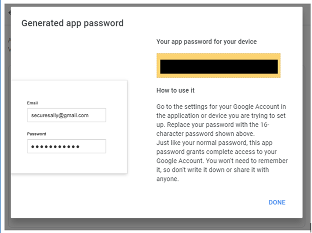
- The App password is the 16-character code in the yellow bar on your device.
Replace your Gmail password on AKCP devices with this password, the other SMTP configurations can be left unchanged.
SEC (securityProbe): Edit the Email notification actions in Notification => Action page, edit system SMTP settings in Setings => System Maintenance page.
SP+ (SP2+ &SPX+): Edit the SMTP settings in Settings => SMTP page.


Important Note: Please keep in mind that in our testing we found that the same, or similar app password can be reused for multiple AKCP base units. However, this depends on Google and whether this will be accepted. We cannot guarantee that the same app passwords will not be rejected by Google in the future when they detect multiple devices using the same app passwords.
Moreover, to avoid possible issues we would highly suggest you create different app passwords for each AKCP device where you need to log into, or for every SP+ or securityProbe’s if you have multiple AKCP base units.
We have tested this feature with our securityProbe and SP+ devices using our testing Gmail accounts and it is working correctly.
First make sure your SP2+ or SPX+ unit is running the latest firmware that is on our website support portal.
Secondly, please make sure you ordered the correct modem type for your region. We offer two types, the EU and US versions. You can check your region using this link here:
https://www.worldtimezone.com/gsm.html
| Frequencies | EU model:
|
| Category | CAT1 |
| Data Transmission |
HSPA+L up to 5.76 Mbps(UL),42Mbps(DL) LTE Category 1: up to 5 Mbps(UL),10Mbps(DL) |
Please also make sure your region & GSM SIM service provider supports the following specifications for our internal modems:
Test the SIM card you are going to use on the SP2+ or SPX+ in your mobile phone to make sure you are able to send the SMS successfully and the SIM has enough credit.
Make sure you have inserted the SIM card into the modem (see manuals) correctly with the power off on the unit. Make sure you have connected the external antenna and that you are receiving a good signal from your GSM provider. Reboot the device one more time and wait a few minutes before testing the SMS notification.
If there is a PIN code on the SIM card, this needs to be disabled. Also double check the settings on the modem are correct. Ensure that you are using the correct DNS settings from your cellular internet provider.
And verify with your cellular network provider what the settings should be for their 3G/4G network.
If you are still having a problem sending SMS alerts, please contact our support team [email protected] and include all troubleshooting details and the “support” file from the unit.
sensorProbe+ Configurations Memory & BEB (Basic Expansion Bus)
Yes, the SPX+ units can be ordered in both 1U and 0U rack mount type configurations with many different configurations and module types. You can check our online configuration tool to custom create your own unit type using the link below, or choose from a variety of pre-set unit configurations.
https://www.akcp.com/configuratorTool/index.php?p=spxplus
https://www.akcp.com/akcp-products/sensorprobe-plus/sensorprobexplus/
Please also check our product datasheets and manuals for more technical details on each SPX+ module.
F7 Units Specifications:
AKCP STM32F7 MCU 32-bit ARM micro-processor 512KB of Ram 32MB of non-volatile flash
H7 Units Specifications:
AKCP STM32H7 MCU 32-bit ARM micro-processor 1MB of RAM 64MB of non-volatile flash
CPU speed: 216 MHz (F7) to 460 MHz (H7) The H7 is significantly faster than the F7 in real usage.
The most notable difference between the platforms is the supported number of sensors when the VPN feature is enabled: the total sensor count is reduced to 36 on F4 units, but it is still 150 on F7 & H7 units.
When upgrading the firmware, there are three separate .bin files included in the firmware update packages. One for the F4 units, one for the F7 units and one for the H7 units. If you try to upgrade your unit with the wrong .bin file, the firmware upgrade will fail. So please make sure you use the correct file for your unit type following the firmware upgrade instructions in the text file that is included in the compressed firmware package.
Also, very important to note that any backup configuration created on the F4 platform cannot be uploaded to the F7 platform unit and vice versa. This also applies to the H7 units. Backup configurations created on the F4 or F7 units are not compatible with the H7 units.
This applies to both the F7 & the H7 type SP+ units. If you require more than 14 sensor graphs then you can use our AKCPro Server software which there are no limitations for the sensor graphs. Our software can be downloaded from this link:
https://www.akcp.com/akcp-products/akcpro-server/
Check to make sure the sensorProbe+ unit is running the latest firmware.
Check to make sure you have connected the BEB extension cable to the correct ports, from the base unit to the BEB unit. Our BEB product manual on our support portal includes this information.
If you have created your own cable, then double check the pin outs in the manual.
Try the extension cable (blue) that was shipped with the BEB unit(s).
Next try these steps:
- Disconnect the BEB cable from the SP+ Gateway.
- Power on the SPX Gateway and wait for it to fully boot up.
- Power on the Remote unit (BEB).
- Long press the Reinit button on the Remote (BEB) unit for about 3-4s until the LED blinks from slow to rapidly then release it.
- Connect the BEB cable to the SP+ Gateway.
- Wait for about 1-2 minutes until the BEB is connected. Act/Sts LED should blink rapidly.
There is also an online YouTube video here that shows this process: https://youtu.be/xJsTGgnT1-Y
After all of this, you still cannot see or access the BEB unit, please contact our support team for more assistance [email protected]
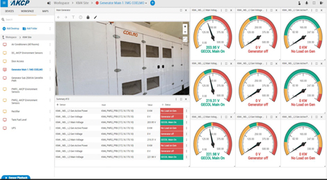
sensorProbe+ Virtual Sensors PMS & Modbus
If you are going to use the Modbus protocol over the RS485 on our SP+ unit(s) to monitor backup generators, then here is some basic information you will need below. If you are not familiar with Modbus, then you would need to check online to learn more about how this protocol works.
For example, if you are planning on using the Modbus RTU RS485, then the register is basically the address for that piece of information.
Let’s say the generators controller has 5 different parameters
– Voltage Output
– Current Output
– Charge Status
– Input Current
– Input Voltage
Each of those would have its own register, to identify it. That way our SPX+ can send a request to the controller by requesting a specific register, the controller then knows what information we are asking for and it can send it to the unit via the Modbus virtual sensors.
You would need to obtain the manual for your customer’s specific generator and also ask them “How do we request information over RS485 from your device?” Then setup each of the Modbus virtual sensors accordingly as explained in the SP+ Modbus manual. You can also check our online video here:
First make sure you have checked the information regarding the setup of the AKCP PMS in our sensorProbe+ Modbus manual on our website support portal and that your firmware is the latest on our website as well.
Next make sure that you have connected the AKCP PMS correctly to the EXP/MOD port using the correct wiring shown in the manual.
Next confirm if you have configured the EXP port to be Modbus on the SP2+E/SPX+. As explained in the manual, by default, the EXP port is configured to be connected to the E-IS8, E-O16 or CCU expansion units, so the RS485 Modbus (AKCP PMS) will not work if this is not changed and saved.
Please check the SP2+E/SPX+ web UI setting by navigating to the Settings > Modbus page then check the following:
Modbus RS485 : Enable
Modbus mode : Master
Then make sure you save this and reboot the unit and follow the setup directions in the manual noted above.
Normally if you purchased any of our products through a local authorized AKCP dealer of ours, we suggest you try and contact them directly first as they would be in your same time zone. When they signed up to be our dealer they agreed to provide direct technical support to you.
If you are having any trouble contacting or obtaining technical support from our local dealer, you can always contact our support team via email [email protected] and we will be more than happy to assist you further.
Please keep in mind we normally only provide technical support during our daily working hours GMT+7 Monday through Friday. We normally will always reply to you within 24 hours.
If you don’t hear a reply back from us within 24 hours, it might be because your email was caught by our spam filter. Or our reply email to you was caught in your spam filter. In which case, please try to use another email address to send from, or a different communication method. And also check your spam filter.
When contacting our support team via email, please always provide all technical information regarding your issue or question and include the troubleshooting details and support file from the unit if you have a technical problem. This will ensure we can get back to you as quickly as possible with an answer or a possible solution.
As mentioned above in this Knowledge Base section, we highly recommend you download, thoroughly check and read the information in our product manuals before contacting us, as these will most likely answer a lot of your questions and hopefully resolve your issues.
Thank you for using and your interest in our products!
AKCP Technical Support Team