Hospital Backup Power Plan – Understanding NFPA 110 Chapter 7
How NFPA 110 can help you plan your hospital backup power system
NFPA 110 provides guidelines for the performance of emergency and standby power systems. It is a requirement for hospitals to provide Emergency Power Supply Systems (EPSS). These supply independent power for critical life support systems and infrastructure. Its intent is to ensure maximum reliability of the EPSS.
In this article, we will examine the requirements of NFPA 110, how to meet them, and what considerations should be made when designing your EPSS. The document refers to the complete powertrain, generator, switchgear, load terminals and fuel storage tanks. By following the guidelines outlined in NFPA 110 you can ensure a reliable alternative power source for your facilities.
Chapter 7 of NFPA 110 relates specifically to EPSS in buildings that provide life-saving critical infrastructure, for example, a hospital. It is imperative that these systems are not interrupted during natural disasters, and power outages. The facilities must prove compliance with local authority regulations and codes. NFPA 110 does not provide certification, it is merely a set of guidelines that, if followed, will aid in the approvals from local agencies in charge.
NFPA 110 defines two levels.
- Level 1 : Where EPSS systems are engaged in the continuity of service for life support systems whose failure would result in the loss of human life.
- Level 2 : Where EPSS systems are engaged in the continuity of service that are less critical to human life and safety.
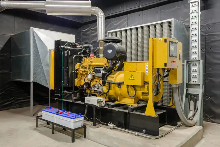
Locating your EPSS
As your EPSS must provide reliable backup power, they should be protected to ensure continued function during natural disasters or fires.
If the EPSS is located inside your main building, they need to be located inside a room that has a minimum fire-resistance rating (FRR) of 2 hours. No other equipment should be installed in this room other than that associated with the EPSS.
Externally located EPSS must be shielded from rains, wind and snow. Shelters for the EPSS should be designed in compliance with local building codes with suitable level of wind and rain resistance. If you are located in areas prone to storms, tornadoes or earthquakes, these should be considered in the shelter design.
The goal whether located inside your facilities or outside, is to protect the EPSS to ensure continued operation when called upon.
NFPA 110 Power Switching Time
NFPA 110 specifies different categories of EPSS. Hospitals fall into the class 10 category. This means that the system should be able to start and restore power within 10 seconds of the main line power failure. In technical terms, it is the maximum time for which the terminals on the transfer switch can go without electrical power.
NFPA 110 Fuel Storage Requirements
The regulation also outlines the recommended amount of fuel that should be stored on-site for facilities engaged in critical life support systems. The amount of fuel required will depend on the duration (number of hours) runtime you need at maximum load capacity without refueling.
Your locations seismic category will also have a bearing on the fuel storage capacity. A low seismic risk (A) to very high risk (F)
Hospital Emergency Power Supply Systems fall in Class X should have a minimum of 4 days (96 hours) fuel stored on site based on the running at maximum kW rating of the generator. In the event of a natural disaster the delivery of fuel replenishment can not be guaranteed and so the ability run at full capacity for several days is vital.
In addition, there is a requirement for the fuel tank to be sized at 133% of the fuel needed. THis means for a large generator you may require 18,000 gallons of fuel for 96 hours operation. +33% results in 24,000 gallons of fuel stored on site. For rural locations where fuel delivery logistics can be difficult, 150% or more oversizing of the tank may be applicable.
As already said, the NFPA 110 does not give a list of requirements that meet your local regulations. However, a good understanding the recommended best practices in NFPA 110 will aid in navigating compliance with your own local regulatory authority requirements.
Diesel should not be stored for more than 12-16 months.
NFPA 110 Temperature Maintenance
In cold climates, it is recommended that the battery and engine water temperature be maintained at the manufacturers specified temperature. This ensures reliable startup and load acceptance, an important aspect of being able to meet the 10 second switchover time. An engine jacket water heater should be installed that is appropriately sized for the engine. Battery performance is affected by temperature and should be monitored.
NFPA 110 Battery Capacity Requirements
The starting system of the generator typically relies on a battery for cranking and startup. NFPA 110 recommends for an EPSS at hospitals the battery should be capable of 3 cycles of canking for a period of 75 seconds each. The battery should be connected to a recharging system that restores full battery capacity within 24 hours. A low battery voltage alarm system should also be installed. An automatic battery charger that keeps the battery trickle charged during standby is required. Monitoring battery charging currents and voltages can be achieved remotely with the installation of sensors.
EPSS Commissioning Test
In order for your EPSS to be certified by your local authority a commissioning test should be performed. NFPA 110 provides guidelines for this test. It should include
- Cold start testing to simulate a real emergency. NFPA 110 7.13.4.1.4 details the cold start test.
- Transferring load from normal power to EPSS. This test will the systems ability to pickup the load in the required timeframe.
- Transfer load from EPSS to normal power. Again this will test the transfer switching time to ensure it complies with the required timeframe.
- After cold start test, the generator should be left to cool for a minimum of 5 minutes before proceeding with the next phase.
- 2 hour load test, to ensure the EPSS is capable of carrying the required load for a prolonged period.
- 30 minutes at 30% of stated generator kW capacity
- 30 minutes at 50% of the stated generator kW capacity
- 1 hour at 100% of the stated generator kW capacity
After commissioning, the generator can be signed off for use. However, continued preventative maintenance is vital to ensure continued compliance and reliability of the EPSS. The maintenance required differs for different models and manufacturers. The maintenance program will be usually broken down into daily checks, weekly and monthly maintenance. Certain events should take place after a specified number of runtime hours.
It is recommended that as a minimum there are two major maintenance events each year. More frequent maintenance is required for EPPS and heavily used standby systems. The preventive maintenance events should include :-
- Load test of the generator
- Multipoint inspection based on the engine manufacturers recommendation
- Fuel tank cleaning and maintenance
- Fluid level checking, top off and changes
You can download a free generator monitoring maintenance checklist here
Generator maintenance monitoring systems
There are different levels of monitoring and options available, depending on your specific site, generator, control panel and requirements.
Modbus Connection – Modbus monitoring for generators
Many popular control panels on commercial sized generators feature a Modbus RS485 or TCP/IP connection. Network-enabled monitoring devices with Modbus capabilities can be programmed to connect with the generator and read many parameters and generator stats. Typically engine speed, oil pressures and temperature, coolant levels, fuel flow, runtime and so on can all be monitored over the Modbus connection.
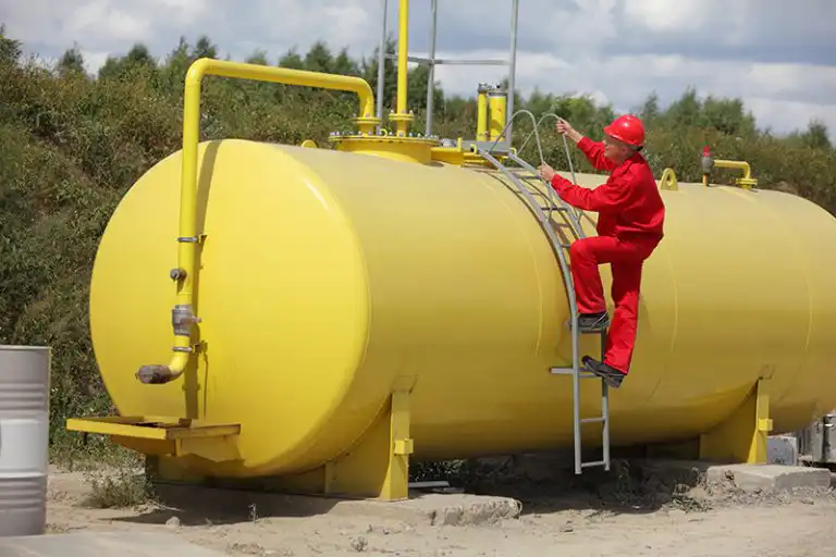
Fuel Level Monitoring
Sometimes, even if monitoring over Modbus, there may be a requirement for additional fuel level sensors to be installed. Generators usually have an internal fuel tank, but this can be small for prolonged operations. Standby fuel tanks can feed these smaller internal tanks. Fuel level sensors placed on these tanks will produce a graph of fuel level and use over time. There are different technologies used for fuel level sensors such as float type, ultrasonic and depth pressure sensors.
Generator Battery Monitoring
A bad generator battery will result in a failure to start condition. Monitoring the voltage and temperature of the battery as well as power output when cranking will give an indication of the batteries health. When you start to see a drop in voltage, increased power consumption during cranking to compensate, you know the battery needs service or replacement.
Power Monitoring and Runtime
Power meters, or Modbus connection, can be used to check the runtime hours and operational loads of the generator. Check you aren’t running close to maximum generator capacity, and check runtime hours to know when to schedule maintenance events.
Generator Alarms
Most generators have digital dry contact alarm outputs. Sometimes these are fixed, or they are programmable through the generator control panel. Alarms for engine over-speed, low fuel, low oil pressure etc. Monitoring devices with dry contact inputs can take in these alarms and alert. Responding to these alarms can be critical to ensure the generator does not suffer further damage. Often alarms can prevent the engine to start at all, so responding to and clearing the alarms is crucial.
Generator Maintenance Monitoring System communications
Many generators are installed at remote sites, or in difficult to reach locations, basements and so on. You must consider the site and the services available when selecting your monitoring system.
Cellular Network Communications
4G / LTE connections are one of the most common to be used for generator monitoring systems. The cellular data modem installed in the monitoring device provides a data link for remote monitoring and sending e-mail or SMS alerts, reports, graphs etc. An advantage of this communications is that you can pretty much put the generator anywhere that has a cellphone signal and begin monitoring. The drawback, however, is that you need a cellular network SIM card and data plan that means recurring monthly expenses.
WiFi or Ethernet Connection
If the location of your generator is within range of your building WiFi network, selecting a monitoring device with WiFi built-in could be an option for you. Sensor data is collected and then sent over the WiFi network for monitoring on your LAN or over the internet.
Where practicable, Ethernet can be used. Running CAT5 cable to some generators may be difficult, but for those nearby the buildings wired ethernet network, connecting to this is a simple and reliable option.
Radio Communication Technologies – LoRa and AKCP Wireless Tunnel
LoRa is a long-range radio network protocol that provides excellent penetration within buildings. The installation of a Modbus – LoRa sensors or other LoRa wireless sensors can be considered. These communicate the data back to a LoRa gateway within range which is connected to the internet by either Cellular Data, Ethernet or WiFi.
LoRa can communicate several kilometers in outdoor open environments, so it is also ideal for getting data from generators in remote sites, pumping stations, or collecting data from multiple generators in a given radius of the gateway.
AKCP has developed standard LoRa, layering on top our own Wireless Tunnel™ protocol. This improves the reliability of the delivery of messages, extended battery life and instant alerts when thresholds are exceeded.
AKCP Generator Maintenance Monitoring Solution
AKCP provides a complete range of tools for generator maintenance monitoring.
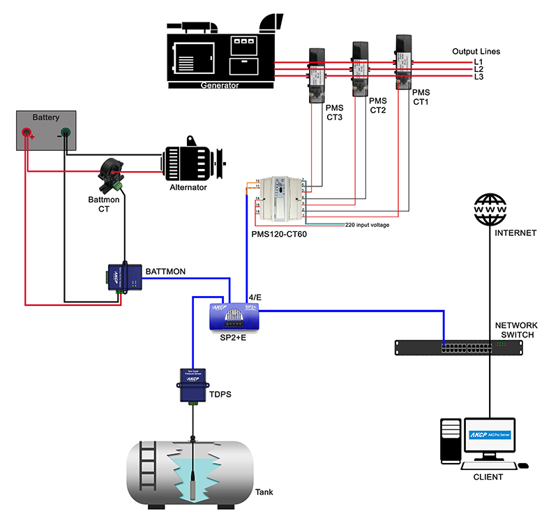
SP2+E
3 sensor port device, with Modbus RS485. Connect to your generators Modus panel, with the option to add sensors such as fuel level sensor, dry contact inputs, battery monitoring sensor. Ethernet communication comes as standard. Optional cellular modem provides remote communication and alerting through the 4G network.
Tank Depth Pressure Sensor
Suitable for tanks up to 20 meters in depth. Tank depth pressure sensors will measure the pressure exerted by the column of fuel above. By entering the tank dimensions the volume is calculated. Fuel tank volume can be displayed and graphed.
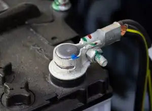
Battery Monitoring Sensor
Monitoring of battery terminal temperature, current and voltage. Ensure your battery is healthy and has sufficient voltage to start the generator when needed.
Dry Contact Sensors
Take in alarms from generator control panels.
Power Meters
1ph and 3ph power meters with current transformers. Check generator power output, frequency and voltage.