The article extolls Calibration of Resistance Temperature Detectors Type Sensors, there is a need to explore a broader subject. This pertains to the calibration of temperature transmitters. We must understand the utility, dynamics, composition, and station of the Resistance Temperature Detectors sensor. From the perspective of the industry that it serves. The RTD is only one of the sensors used in its field, and it would be a travesty to omit the others that serve a similar end. In this vein, we will discuss 5 useful setups on how to calibrate a temperature transmitter. Note that the segment which talks of the calibration of RTD type sensors is brimming with more data. Because this is the central focus of this article. We hope this gives ample justification for the scope of the article here presented. One can better understand RTDs with the entirety of this work. Without the corresponding attachments to this article, it would be hard to put the Resistance Temperature Detectors in its place.
5 Set-ups to Calibrate a Temperature Transmitter:
1. Actual Temperature Simulation Using Metrology Well
Metrology well is a device created to generate an actual temperature. It utilizes a temperature controller with a reference sensor. It is also called a Temperature Calibration Bath. It can be wet when it uses a liquid as a medium for temperature transfer. It can also be dry when using a metal block with a metal insert to transfer the generated temperature. This is the easiest calibration set-up that utilizes a loop calibration. Insert the transmitter probe into the Metrology Well. Then proceed to compare the readings shown in the PLC display panel. But, one major drawback to this method is that it takes longer to get a precise temperature reading. You need to stabilize the temperature for every set point.
Within the Metrology Well is a metal insert with different-sized holes. Pick the correct size of the hole for the probe, a perfect fit and depth will assure the most accurate results. Primed, the Metrology Well will simulate the required temperature on the PLC panel. 2. Actual Temperature Read-Out using a Fluke 754 Process Calibrator
A Fluke 754 Process Calibrator is a power multifunction documenting calibrator. It downloads lists, procedures, and instructions created with software. It can also upload data for printing, archiving, and analysis. It has a HART interface that is capable of performing all tasks with a separate communicator.
This method utilizes two reference standards: the Metrology Well for heat generation and the Fluke 754 Process Calibrator for display. This is when the transmitter connects from the loop or if a bench calibration is necessary.
In this technique, the RTD sensor detaches from the transmitter (Endress+Hauser TMT180). It then connects to Fluke 754 input probes in a 3-wire connection. This allows it to measure the signal from the RTD sensor. It immediately displays it as temperature. The Fluke 754 will now serve as the display of the temperature transmitter. The Fluke Metrology Well gives off the required temperature. One can now compare the reading from the Metrology Well to the one displayed on the Fluke 754. In the absence of a Metrology Well, one may still use this method. Consider a 1 point verification of the . It will serve as the sole present user range, making the Fluke 754 the only reference standard.
3. Direct Temperature Simulation of Electrical Signal Using a Process Calibrator
The Fluke 754 comes with an RTD calibrator, able to simulate temperature and resistance signals, which can communicate with the transmitter input terminals.
No need to convert because the Fluke 754 can simulate a direct temperature signal to the PLC display.
4. Direct Resistance to Temperature Simulation Using a Resistance Box
Because it utilizes an analog signal, this is the most cost-efficient method of calibrating a temperature transmitter. It is also one of the most traditional methods of reading a temperature transmitter.
Resistance Temperature Detectors or RTDs give out readings based on the changes in the levels of resistance caused by temperature change, this, in turn, displays a value with assigned temperature output. They give off an analog signal in the process.
The analog signal comes from a device comprised of resistances called the resistance box, which simulates the varying resistance levels required in the process. This method is also a good way to do a loop check.
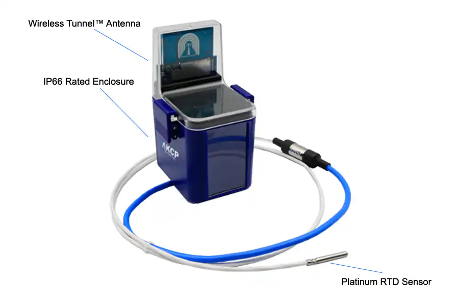
One of the most accurate temperature sensors is the PT100. It consists of a length of fine coiled wire. Wrapped around a ceramic or glass core, it is often placed inside a sheathed probe to protect it. Not only does it boast accuracy, but perfect stability and repeatability as well. It’s the perfect tool for temperature measurement in industrial settings because it’s electrical-noise-proof. There are two types of RTDs, one contains thin-film elements, while the other consists of wire-wound elements, both exist for specific environments and applications.
C.W. Siemens invented the first-ever resistance thermometer in 1860, made of insulated copper wire, a battery, and a galvanometer, it dawned on him that a platinum element produced more precise measurements at wider temperature ranges. To this day, platinum is still the foremost material used for the manufacture of RTDs.
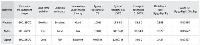
The two standards for PT100 RTDs are the European or IEC standard, and the American one. The former serves as the worldwide benchmark for platinum RTDs. It must have an electrical resistance of 100.00 O at 0℃. A temperature coefficient of resistance (TCR) of 0.00385 O/O/℃ between 0 and 100℃ is also required.
If you’re using a PT100, you can compute the precise resistance to a temperature conversion.
Remove the RTD connection from its place in the transmitter. Replace it with the probe from the resistance box terminal and turn the knob. Set it to a known resistance value with its corresponding temperature. This will generate the required resistance value.
The formula below converts the temperature value to the resistance value. which can serve to stimulate the RTD Temperature Transmitter with the parameters shown:
A Temperature Coefficient of Resistance (TCR) or alpha of 0.00385
A reference temperature of 0℃
RV = unknown resistance value needed
5. Actual Temperature to 4 to 20 mA Readout
Transmitting the temperature output reading from the sensor requires conversion. It must translate to the PLC Display. Convert temperature output into a current signal, which is the 4 to 20 mA. You can immediately read a current output. The transmitter is converting the temperature value to a current. It shows in the display panel. You can confirm its accuracy by doing a temperature to current conversion.
Connect the current meter in series to the supply line, or use the HART function of Fluke 754 in certain transmitters to calibrate in the transmitter supply terminal.
Here is the conversion formula for Temperature to Current:
mA value = Displayed Value of Temperature X16 + 4
Maximum Range
You can also use thermocouples as sensors for temperature transmitters, the same as RTDs, this is especially useful when temperatures exceed 1000℃.
All these methods may serve for calibrating temperature sensors using thermocouples, except for Number 4, which utilizes a resistance box. Only in the simulation part of the Process Calibrator will there be a difference, because thermocouples use voltage signals, while RTDs use Resistance.
Having described these 5 methods of calibration, I will not belabor the obvious necessity of a Temperature Transmitter for monitoring. It is important to note that familiarity with these methods can help you cut costs and free up much-needed capital for other essential equipment, not to mention the invaluable factor of safety that these techniques bring to the equation. There is no need to use all these methods, two at a time is more than ample, and the rest can serve for simple verification. We hope this article proves useful to you.